LIRIS
Long-slit
Intermediate
Resolution
Infrared Spectrograph
for the WHT
|
|
GENERAL
DESCRIPTION
|
LIRIS is an Instituto de Astrofísica de
Canarias (IAC) project that consist a near-infrared (0.9-2.4 microns) intermediate
resolution spectrograph (R=1000-3000), conceived as a common user instrument
for the WHT at the Observatorio del Roque de los Muchachos (ORM La Palma).
LIRIS will have imaging, long-slit and multi-object
spectroscopy, coronography and polarimetry working modes. Coronography
and polarimetry, will be upgrades not available at first phase. Image capability
will allow easy target acquisition.
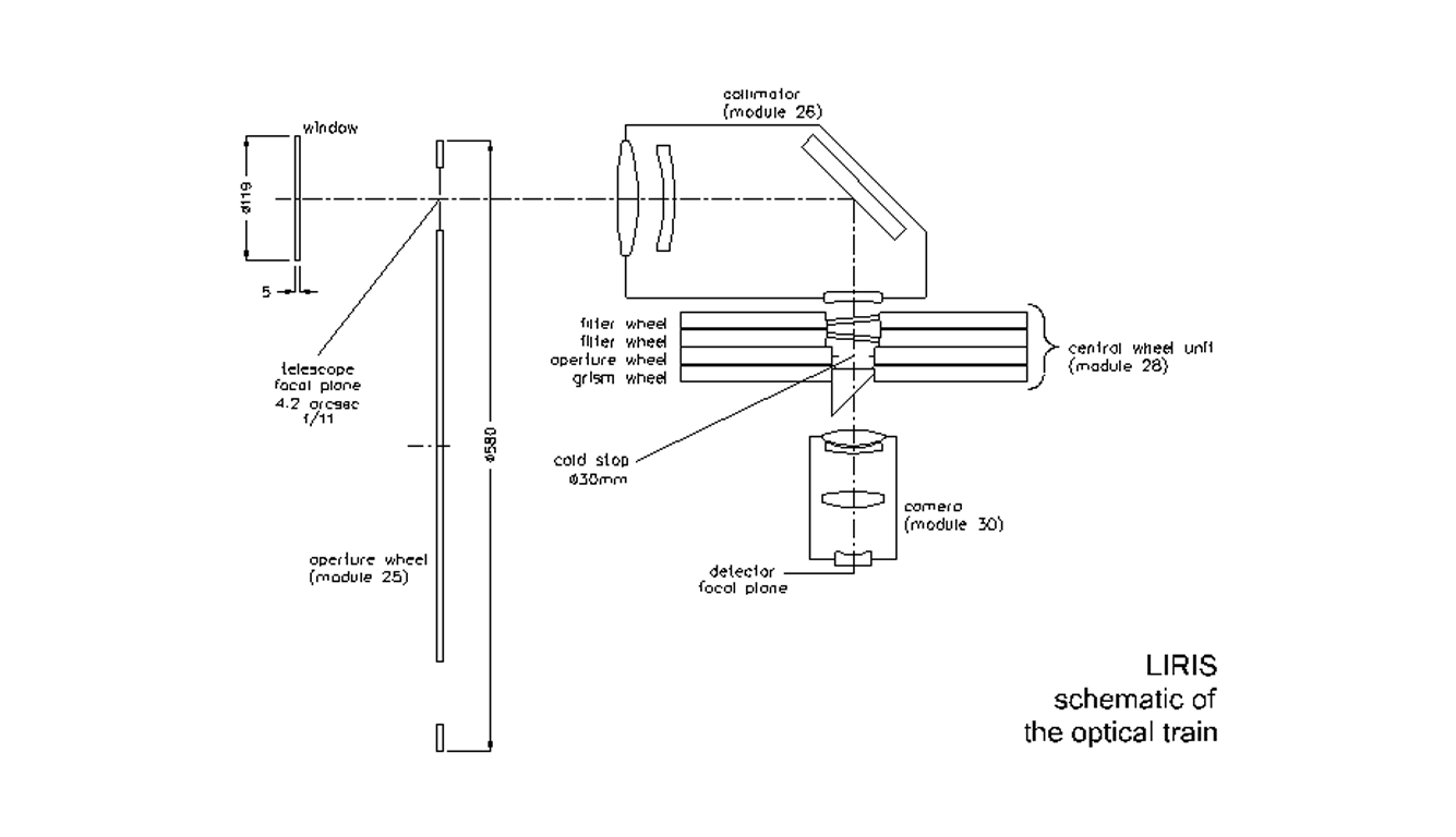
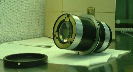
The optical system is based on a classical collimator/camera
design. Grisms are used as the dispersion elements. The plate scale (0.25
arsec/pixels) matches the median seeing (0.5
arcsec in the K band) at the ORM. The detector is a Hawaii 1024x1024 HgCdTe
array operating at 65 K.
|
|
Functional scheme
|
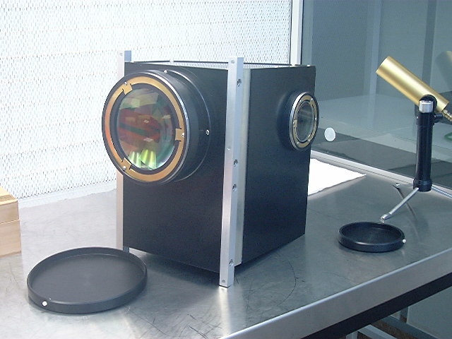
The collected light beam passes through a fused Silica
window. The telescope focal plane lays inside the cryostat, where the cold
aperture masks are located.
The optical design for LIRIS contains the following
main components (see graph below):
-
A slit wheel is introduced at the telescope
focal plane for spectroscopy.
-
A refractive collimator forms an image of the
primary mirror near the last element and produces a collimated beam where
the filters, grisms and Wollaston prisms are inserted.
-
A cold stop: The entrance pupil of LIRIS is the primary
mirror of the telescope, given the fact that the secondary is oversized
with respect to the primary in the WHT, contrary to an optimized infrared
telescope.
-
The collimated beam passes through the pupil.
-
A refractive camera is used to focus the light
onto the detector.
The optics of LIRIS are all refractive, with
the exception of a single folding flat mirror in the collimator assembly.
The expected throughput (averaged across the wavelength range) for the
optics is 80% and 64% in imaging and spectroscopic modes, respectively.
The grism transmission is assumed to be 80%.
The detail optical design and the conceptual
mechanical design were subcontracted to the ROE (Royal Observatory of Edinburgh).
Slit wheel |
 |
|
|
Collimator
|
 Pupil wheel
|
 Camera
|
LIRIS schematic of the optical
train (provided by UKATC/ROE)
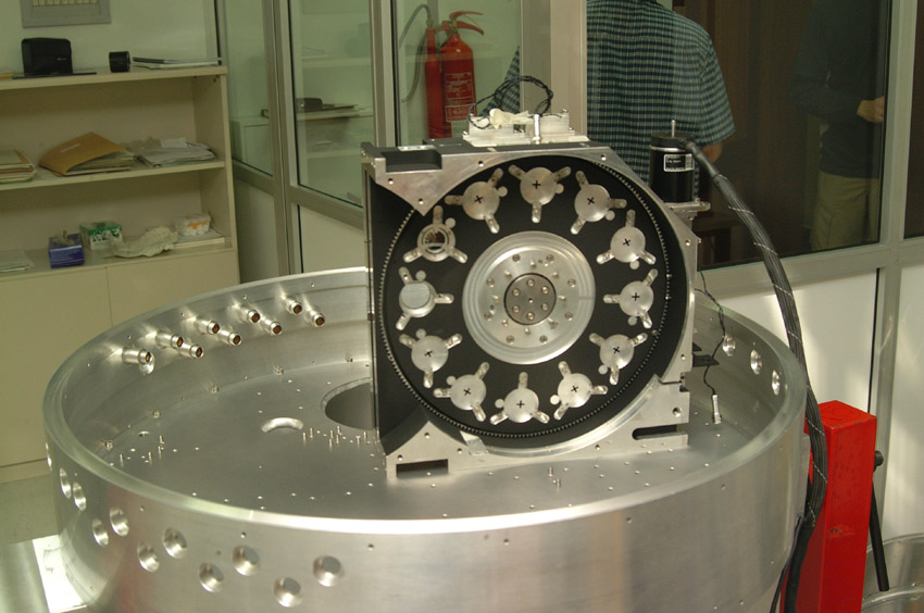
The mechanical design is based on a modular concept,
integrated by the following modules: the aperture wheel (slit wheel), the
collimator assembly, the central wheel assembly (formed by two filter wheels,
the pupil wheel and the grism wheel), the camera wheel and finally the
detector assembly with its focusing mechanism.
The slit wheel contains 16 positions:
1 blank position, 5 long slits (widths 0.65, 0.75, 1, 2.5 and 5 )
plus 10 multislit positions.
The two filter wheels contains 12
positions each, and will hold the filters and the Wollaston prisms.
The pupil wheel contains 12 positions
and will hold the pupil masks, plus an optional apodization mask with rotation
mechanism for coronography capabilites.
The grims wheel has 10 positions for grisms.
The camera wheel will carry the camera
and the optics to image the reimage the pupil onto the detector plane.
The detector will be mounted in a cold translation
mechanism (focus mechanism) to compensate for non-achromaticity
along the observing spectral range.
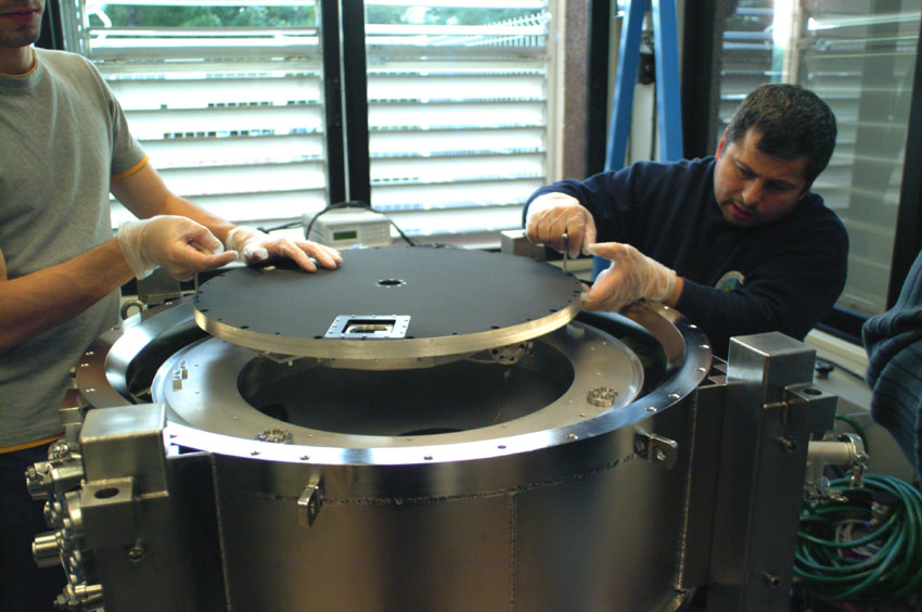
The vacuum vessel is a welded cylindrical vessel.
It is made in three sections, a central ring and two end covers. The front
cover is a circular plate which carries the window and its mounting and
a cover over the port giving access to the entrance wheel. It is not necessary
to remove the front cover to change focal plane masks. The rear cover could
be removed to gain access to all the other internal modules of the instrument.
It has an auxiliary access port to facilitate the first integration &alignment
steps without detector.
The center section carries all the semi-permanent
access ports. These carry ports for electrical wiring, cooling and vacuum
pumping
The optical bench is an aluminium welded structure,
supported from the front ring of the central section of the vacuum vessel
by three trusses made from G10 glass-epoxy composite. It has a cylindrical
shape and its plates acts as a reference surfaces and mounting for all
the cold modules. The bench will be also used as a tank for LN2 for pre-cooling
the instrument. The front plate supports the entrance wheel. The rear plate
supports the rest of the cold parts. The optical bench is fitted with a
panel heater to allow a controlled warm-up while still under vacuum.
The instrument is precooled with LN2, and the
cooling system is a closed-cycle refrigerator (CTI model 1050C), which
works on the Gifford-McMahon cycle. There two stages which provides cooling
powers of 45W at 60K and 4W at 15K. The first stage cools all the internal
parts, except for the detector and its housing. The second stage mantains
cool the detector at the working temperature of 65K. The detector
temperature is stabilized using the commercial PID controller Lakeshore
340.
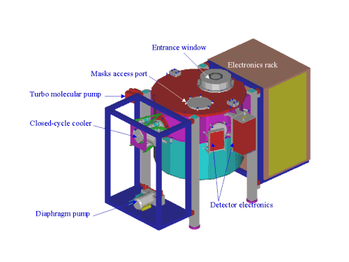
External schematic view
|
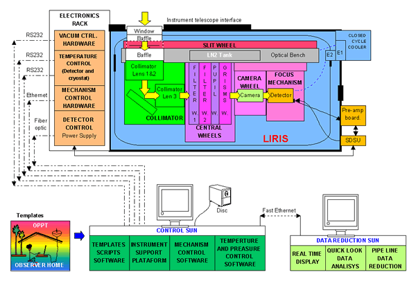
The LIRIS mechanism are driven by cryogenic stepper
motors. The control system is based on a VME system with a Motorola CPU
card running VxWorks operating system and two Oregon Micro Systems stepper
motor controller boards, allowing a total number of twelve motors to be
controlled, each one of them with its own home, limits and power off signals.
The VME system is connected to the SUN through an Ethernet network and
an RS232 line. An additional 19" 3U rack with the motor drivers are installed
under the VME rack. The drivers are from the same manufacturer as the motors'
Phytron.
An agreement has been established between the
IAC and the ING to develop jointly the Mechanism Control Software and the
detector control system for the two infrared instruments (LIRIS/IAC and
INGRID/ING).
The detector is a Rockwell
Hawaii 1024x1024 HgCdTe array. The pixel size is 18.5 mm,
which corresponds to a plate scale of 0.25 arcsecond on the sky.
The quantum efficiency of the detector is larger
than 60% according to the manufacturer. The minimum readout noise is less
than 10e- using double correlated sampling. The dark current is very
low, less than 0.03 e-/s, which implies less than 100e-/hour. In most observing
conditions the LIRIS sensitivity would be limited by background photon
noise. The readout noise will be a limiting factor only in the high resolution
spectroscopy mode.
The controller system uses the SDSU controller,
which is a commercial product developed by the San Diego State University
(SDSU) and supplied by IRLabs (Tucson, AZ). It is based on the 56200 DSP
by Motorola. The current code was developed by P. Moore of the Isaac Newton
Group for the INGRID project. The detector is read through four channels
at a rate of 3 msecs/pixel, leading to a time
of 0.9 seconds for a complete frame readout. The SDSU controller communicates
with the control computer through optical fibers.
The available read out modes are double correlated
(DC), Multiple non destructive reads (MNDR) and reading up the ramp.
A temperature controller is required due to the
strong dependence of the signal offset level of the detector with
the substrate temperature. For this reason the detector temperature has
to be stabilized below 0.005K. The temperature controller Lakeshore
340 has been selected, which guarantees a stabilization below
0.005K, sufficient to constrain the offset variation to 0.1e- RMS.
The LIRIS Software system is being designed to be
fully integrated in the observering environment available at the WHT. A
common observer will have access to the following software packages:
Instrument Simulator Software: Given the
source characteristics (expected brightness, extended or point source,
sky brightness) and an observing mode (imaging or spectroscopy, dithering
or beam switching), a LIRIS simulator will be used to obtain the
S/N ratio for a given integration time or viceversa. It will also provide
the instrument configuration suitable to carry out the desired observation,
i.e. it will be able to generate the templates which can be interpreted
by the Template Generator Software (described below). It will
also have access to whole sky standard catalogues (POSS, 2MASS, IRSKY)
in order to simulate what is included within the LIRIS aperture (it is
especially important for background positions and spectroscopic observations).
This component may be accessed by general observers at any place, as an
HTML application.
Templates Generator Software: This
package will be used to define the LIRIS observing parameters. It will
have a set of predefined modes, called templates, adequate
for the most common types of LIRIS observations. Each of them will
have a number of configurable parameters (exposure time, detector reading
mode, filter selection, etc). This system will generate a sequence
of commands or scripts which can be interpreted by any of the systems available
at the Instrument Support Platform.
Instrument Support Platform User Interface:
This
package will be the main User Interface for LIRIS. It will provide the
support infrastructure required to operate the instrument, including facilities
to set up exposure parameters, data acquisition from the instrument detector,
pointing the telescope, and also the execution of LIRIS Observing Templates.
LIRIS Mechanism Control Software: This
system can receive commands from the Instrument Support Platform and return
status information. It comprises the following 2 subsystems:
LIRIS EPICS Mechanism Control Software: This
system is the responsible of the direct control of the LIRIS
mechanisms (slit, filter, pupil, grism, camera wheels and detector
focus). This software will run on the VME EPICS rack.
Temperature Controller Software: This
system will be used to control and monitor the detector temperature. ..
Real Time Display: This tool will be use
to monitor the newly acquired images. It will basically process and
display them using Ximtool / SAOtng as display device. These
tools offer facilities to change color tables, zoom, several image frames.
It will also provide some facilities: basic statistics, different
scaling of the representation, and additionally there will be a seeing
and background monitor.
Quick Look Data Analysis: This package
will provide facilities for a quick analysis of the recently acquired
data. This should include facilities to perform sky subtraction, coaddition
and alignment of images, extraction of spectra, default wavelength calibration.
It will be based on existing astronomical data analysis packages, like
IRAF.
Pipeline Data Reduction: This package
will be used to process blocks of images obtained through the LIRIS Observing
Templates. It will receive notifications of available data blocks
from the Instrument Support Platform in order to start the processing.
The following steps will be done: detector effects removal, flat-fielding,
sky subtraction, coaddition and alignment of images. For spectroscopy there
will be a default wavelength calibration.
 Back
to the Home page
Back
to the Home page
Last modified: 08/03/02
Page mantained by: Jose Acosta and
Mary
Barreto